
Check estimated delivery
8051 8-Bit MCU, Micro-Controllers
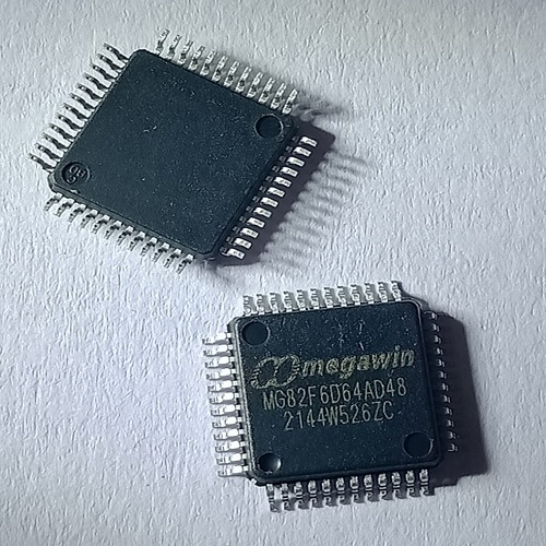
Megawin 8051 MCU MG82F6D64AD
SKU: Megawin 8051 MCU MG82F6D64AD
₹177.00/per piece₹1,770.00
₹1500 + 18% GST
incl. GST
Pack of 10pcs
Availability: Available on backorder
Estimated Delivery: Estimated delivery in 2 to 4 weeks
For bulk orders or B2B inquiries, email us: sales@empere.in
| Qty | Unit Price | Total Amount |
|---|---|---|
| 1 Pack (10 pcs) | ₹177.00 / pc | ₹1,770.00 |
| 10 Packs (100 pcs) | ₹177.00 / pc | ₹17,700.00 |
Prices include 18% GST.
Standard Packaging
10 pcs / Pack
| 1T 8051 MCU Flash ROM: 64 KB RAM: 4096B IO’s: 59 Timer: 5+RTC Communication: UART x 4, SPI, TWI(I2C) x 2, STWI, LIN, CRC16 Packages: LQFP-64 , LQFP-48 |
Megawin 8051 MCU MG82F6D64AD
Flash ROM64 KB
RAM4096B
IO's59
Timer5+RTC
CommunicationUART x 4, SPI, TWI(I2C) x 2, STWI, LIN, CRC16
PackagesLQFP-64 , LQFP-48
| 1-T 80C51 Central Processing Unit | |
| MG82F6D64 with 64K Bytes flash ROM |
|
| AP Flash default mapping (61.5KB, 0000h~F5FFh) | |
| IAP Flash default mapping (1.0KB, F600h~F9FFh) | |
| ISP Flash default mapping (1.5KB, FA00h~FFFFh), ISP Boot code | |
| Data RAM |
|
| Dual data pointer | |
| External Memory Bus interface (EMB) |
|
| Provide one channel DMA engine |
|
| Interrupt controller |
|
| Total 14/ 17(with split mode) timers in MG82F6D64, and total 13/15(with split mode) timers in MG82F6D32 |
|
| 7 16-bit timer/counters, Timer 0, Timer 1, Timer 2, Timer 3, Timer 4 , Timer 5, Timer 6 |
|


Leave a Reply