
8051 8-Bit MCU, Micro-Controllers
Compare
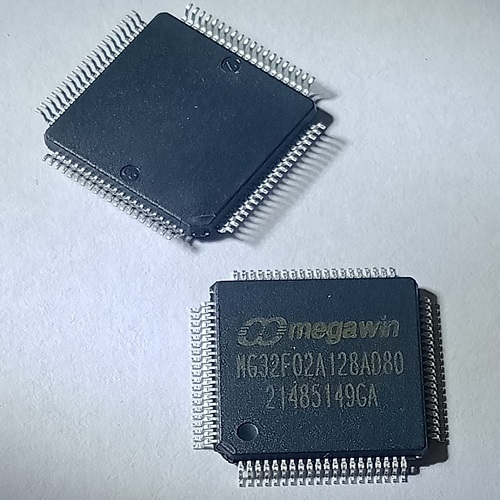
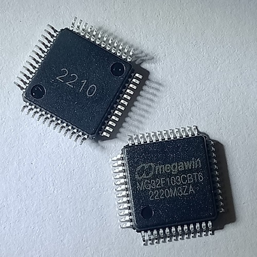
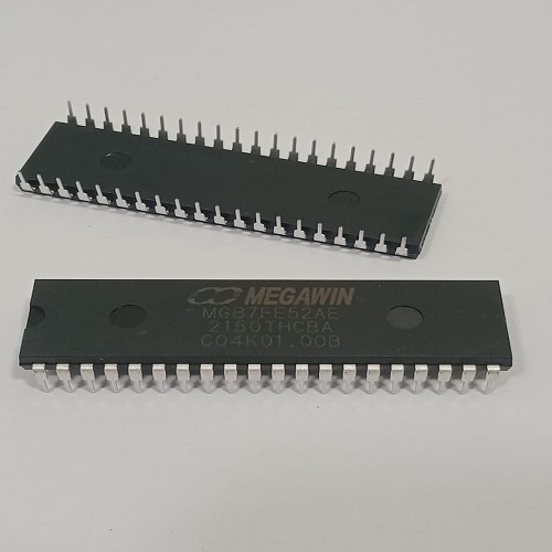
Megawin 8051 MCU MG82F6D17AE20
Availability:
15 in stock (can be backordered)
1T 8051 MCU
|
₹53.10
₹45 + 18% GST
incl. GST
Availability: 15 in stock (can be backordered)
15 in stock (can be backordered)
- 1-T 80C51 Central Processing Unit
- MG82F6D17 with 16K Bytes flash ROM
- ISP memory zone could be optioned as 0.5KB/1.0KB~7.5KB
- Flexible IAP size by software configured
- Code protection for flash memory access
- Flash write/erase cycle: 20,000 times
- Flash data retention: 100 years at 25℃
- Default MG82F6D17 Flash space mapping
- AP 13.5KB 0000h~35FFh
- IAP 1.0KB 3600h~39FFh
- ISP 1.5KB 3A00h~3FFFh
- Data RAM : 1K Bytes
- On-chip 256 bytes scratch-pad RAM
- 768 bytes expanded RAM (XRAM)
- Support page select on XRAM access
- Dual data pointer
- Provide one channel DMA engine
- P2P, M2P, P2M
- Memory target: XRAM
- Peripheral target: UART0, UART1, SPI, TWI0/I2C0, ADC12 & CRC16
- Timer 5 and Timer 6 are used for DMA, but it also can be traded as independent timer when DMA not in use
- Interrupt controller
- 16 sources, four-level-priority interrupt capability
- Three external interrupt inputs, nINT0, nINT1 and nINT2, with glitch filter
- All external interrupts support High/Low level or Rising/Falling edge trigger
- Total 9/10 timers in MG82F6D17
- RTC Timer and WDT Timer
- Timer 0, Timer 1, Timer 2 and Timer 3
- PCA0, Program Counter Array 0
- S0 BRG and S1 BRG
- If Timer 2/3 in split mode, then total 10 timers
- Four 16-bit timer/counters, Timer 0, Timer 1, Timer 2 and Timer 3
- X12 mode and timer clock output function
- Synchronous Run-Enable on all timer (same function on Stop and Reload)
- New 5 operating modes in Timer 2/3 with 8 clock sources and 8 capture sources
- Timer 2/3 can be split to two 8-bit timers
- Clock Count Output (CCO) on T2CKO and T3CKO
- All timers support PWM mode

Leave a Reply